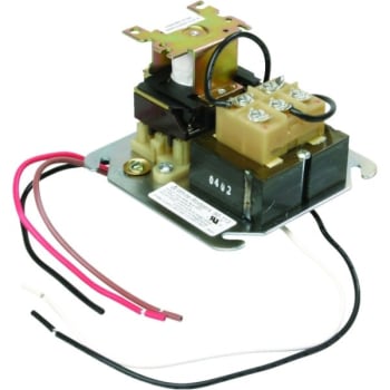
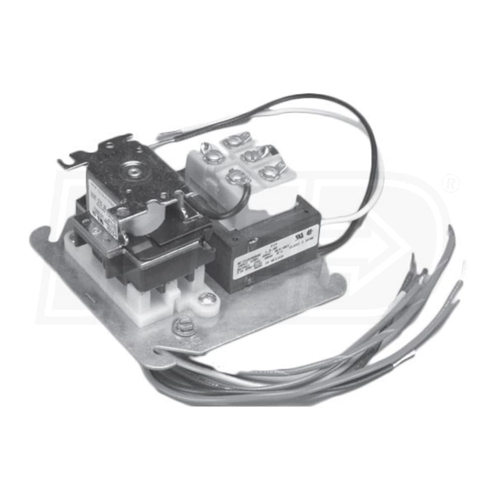
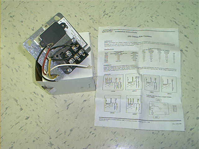
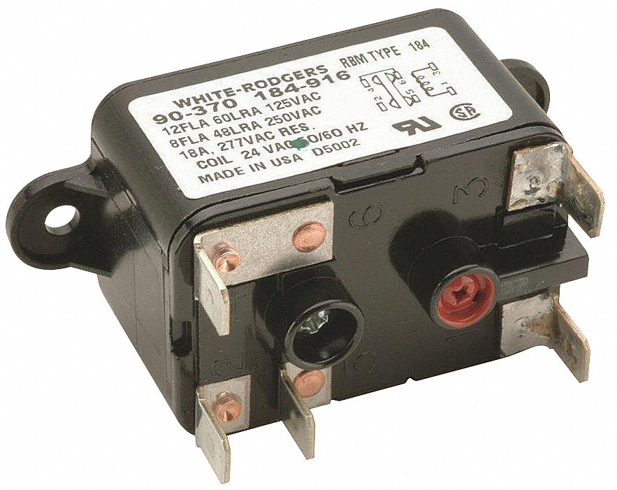
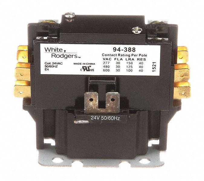
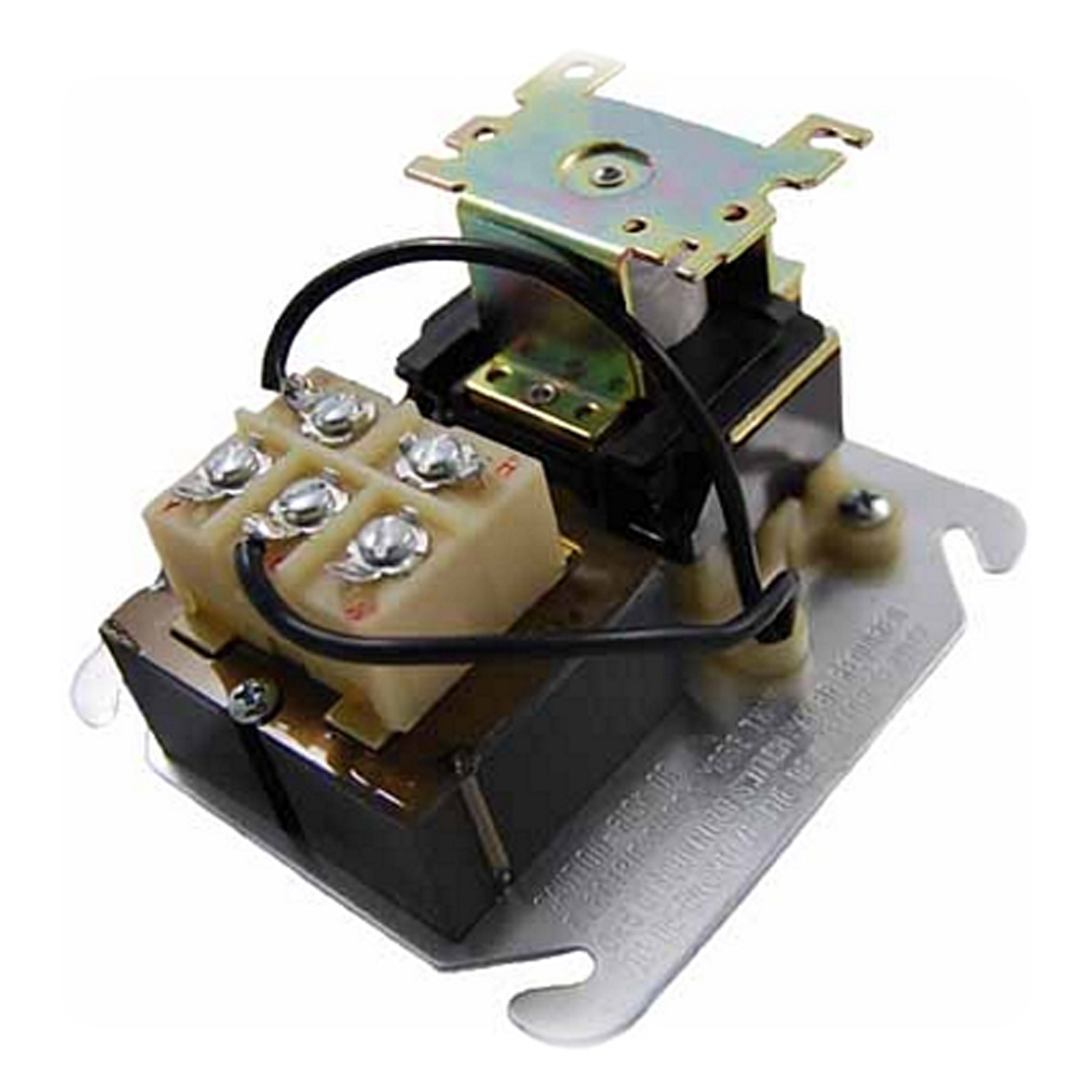
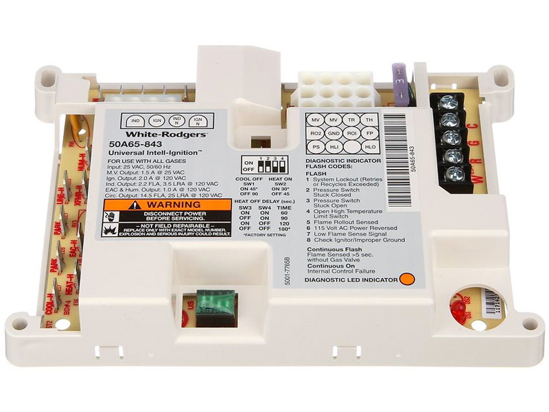
The 90 113 white rodgers fan control center relay is a brand new oem white rodgers fan center relay that comes packed in a white rodgers factory box.
White rodgers fan control center relay model 90 113.
Fan center relay is to provide low voltage control 24 volts of line voltage circuits 110 volts.
Icp heil tempstar fan relay control board hq1005229wa 1065750 new part number 11 17 2016 heating element.
Br many of the newer furnaces do not have fan center relays but many of the older furnaces and some new furnaces still do.
White rodgers 15 23 49 each add to cart.
I m replacing an old a o.
Br you would need to look inside your furnace to determine.
Features an energy limiting class ii transformer design and color coded pre stripped leads.
Smith fan motor model dl1036.
The white rodgers fan control center relay 90 113 is used on many furnaces to control the fan blower when you set the thermostat to fan on position or when you want the blower.
Grainger s got your back.
Includes low voltage connections on terminal board.
White rodgers fan control center relay model 90 113 85 00 63 75 45.
Easy online ordering for the ones who get it done along with 24 7 customer service free technical support more.
Looking for white rodgers transformer relay 4x4 junction box mount 24 coil volts spdt 3 4 hp hp 2e852.
Fan control center 120 vac primary 24 vac secondary spdt relay 90 113 fan control center 120 vac primary 24 vac secondary spdt relay.
For a white rodgers rbm transformer relay dpdt 120 24v second fan center.
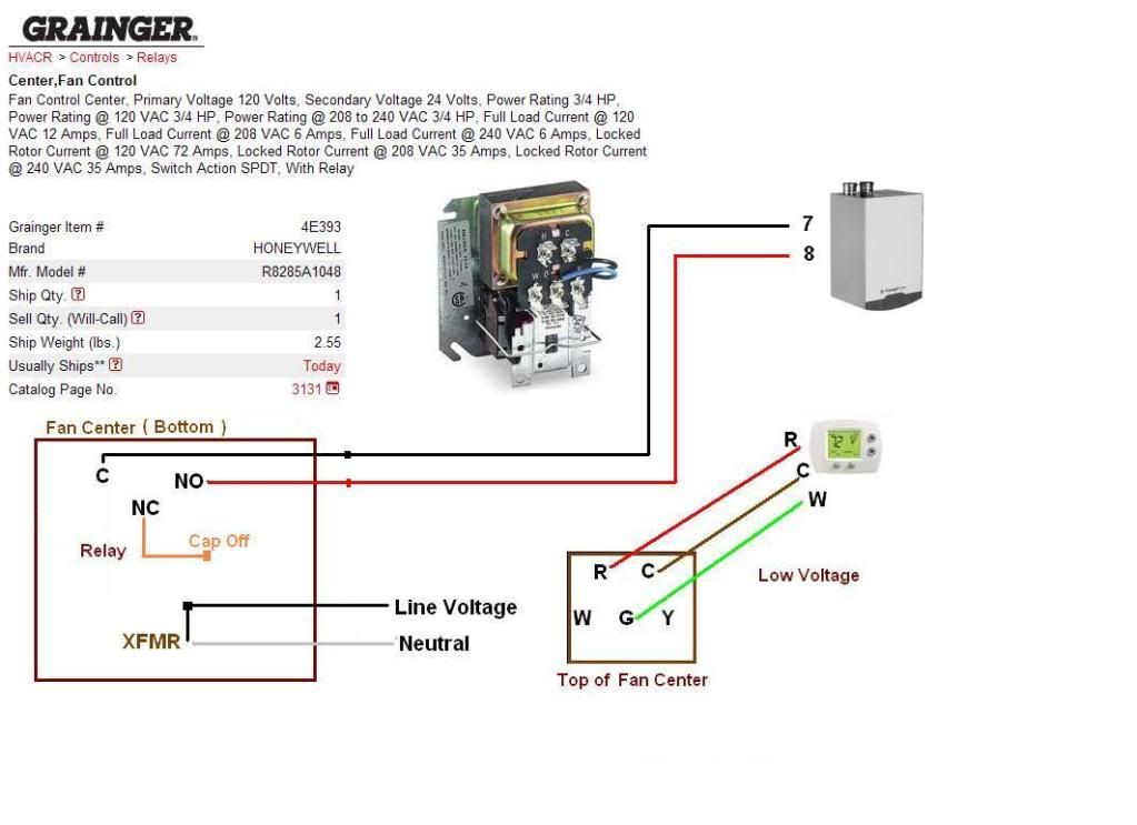
A wiring diagram is a streamlined conventional photographic representation of an electrical circuit.
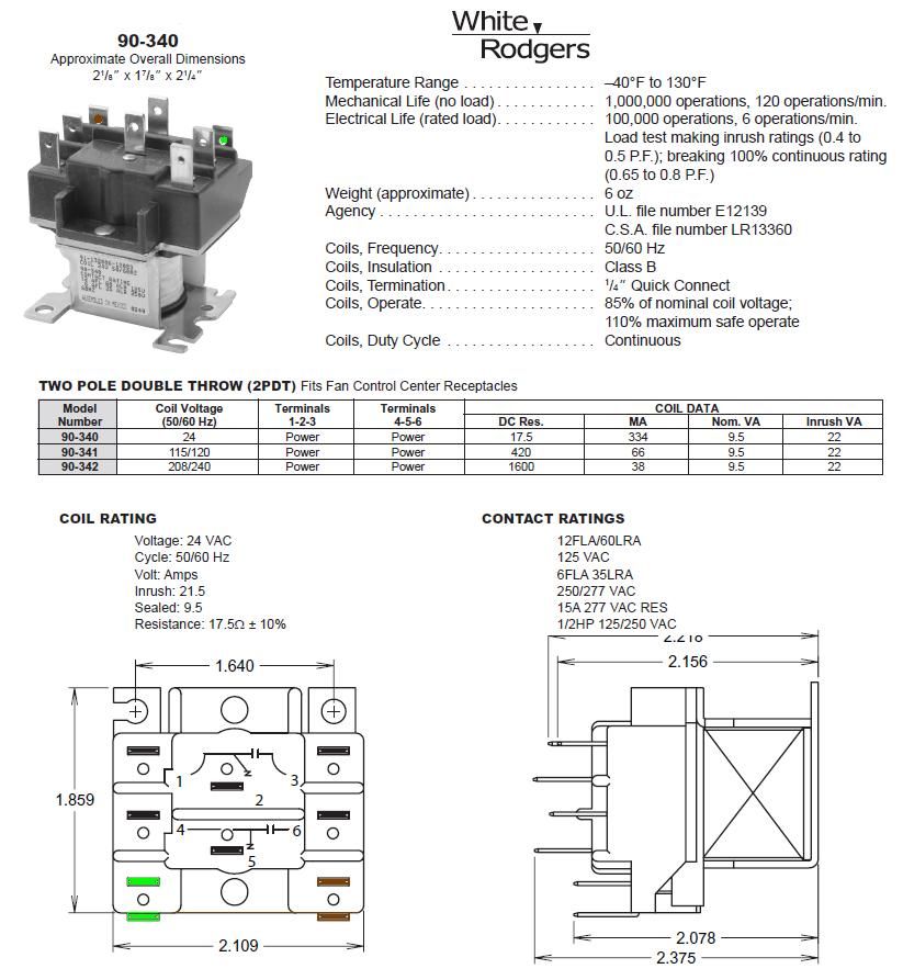
Br can be used to control two speed blower motors and auxiliary circuits in heating or cooling equipment.
Collection of white rodgers 90 113 wiring diagram.
Basically all i am using it for is to turn the pump on off as needed by the thermostat.
02 10 2018 02 10 2018 4 comments on white rodgers 90 113 wiring diagram i m replacing a white rodgers fan control on my furnace.
Fan center relay 8 condensate pumps float safety switch 17.
Line voltage connections are pre wired.
The original heater diagram shows one side black v but i can t figure where black from relay goes where the black for transformer goes 3 wires in that.
Tue sep 29.
It reveals the components of the circuit as streamlined shapes as well as the power and signal links in between the gadgets.
